This is a tank I built with radio control. It was one of the things I made when I got tired of the Hercules. Sidetracked is the common term for it.
Facts
The tank uses an old radio control from Sanwa that I used to fly model airplanes with. I took the servos and stuff and LEGOlized them in order to manipulate the polarity switches found in the 8480 Space shuttle.
I used five servos, five polarity switches and five 9V motors. Two of the motors was the micro motor also found in the 8480 Space shuttle sets. Did I mention I like the 8480?
The tank is built mainly in white since almost all my black parts were used to build the wing of the Hercules and to make a "snow camouflaged" tank. The first snow for the winter 2000/2001 was falling outside you see.
I dubbed it "Lynx" 'cause I really like that animal and it's pretty common up here where I live (Sweden in Scandinavia). Also the Lynx is a powerful animal that is quite happy with the snow, I think :)
I'm not sure why I wanted to build a tank now six months later, but I did.
The tank had the following functions:
- Dual caterpillar treads for movement and steering. Powered directly (1:1 gear ratio) by a 9V mini motor (the type that comes with the Mindstorms kit). One for each tread. The motors were controlled by polarity switches that in turn was controlled by my servos. I used the rare chain link type treads mostly to show them off.
- Turret that could spin 360-degrees and beyond. The limit was when the electrical wires got too tangled, it never happened so I imagine it would have taken a lot of spinning on that turret... The turret was powered by a third 9V mini motor and pol. switch/servo combination.
- The gun in the turret could be raised lowered using a micro motor and pol. switch/servo.
- The cannon could be fired using the second micro motor.
So, all in all the tank had what it took to be remotely operated and hunt our cats or sneak up on my coworkers. They got really scared (the coworkers, not the cats. What do you take me for?) when I made surprise attacks on them.
The tank had two limits: 1. The treads did not have enough friction to drive over doorsteps. 2. The lower/raise part of the cannon was painfully slow and took the surprise effect away from shooting at my coworkers. I did manage to get around limit #2 slightly by raising the cannon before driving into their offices.
The tank also delayed my main project, the Hercules. I wanted to take some pictures of the tank in snow (the snow that fell the day I built it quickly melted away over night) so I waited the longest time for a holiday (I needed the light) with snow, but it never occurred. So I tore the tank down about a month after finishing it, and see! The snow fell. Define irony the one who can ,) (It's really when the word opposite the real life).
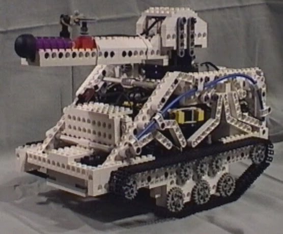
We start our graphic tour of the Lynx by displaying the whole thing. Note the whiteness on everything but the cannon. I'd like to have one of these in another color like white or black. Yes, I know they exist I don't think the sets carrying them is worth the money though.

Moving on to the back. Nothing much to say here really. You'll see a better shot of the micro motor raising/lowering the cannon further down on this page. Promise.
Just so say something, the back has a nice flat surface to allow missiles and grenades make a better impact on the tank. Modern tank have non 90-degree (measuring from the ground) armor to make grenades bounce off and to be more invisible on radar.

Tipping the tank on it's side displays the under carriage. It's pretty flat to make it able to skid over rough terrain. Now if only the treads could stop skidding. Just kidding. Oh my God, I'm lame..
Moving on folks!

As promised, here is the micro motor that drives the axle that turns the worm gear that drives the z24 gear fixed to the cannon that makes the cannon raise or lower. Oh, I mentioned it's a slow-motion thingie right? Also, did I mention that English grammar ain't my strongest side?

Here is a photoshoped image of the cannons extensions. To travel the whole distance the tank needs 26 seconds. Now that's slow!
If you didn't understand my comment on the previous picture, this movement is what the micro motor does.

Here is the cannon itself with the trigger. When the micro motor spins it tightens the rubber band enough to pull the trigger.

Here is a view of the front. Don't mock with it ,)

This is how much ground clearance the tank had. The bottom is nice and flat.

This shot shows the main motors that drove the treads. As you can see they drove them directly with no gears. To save the motors it was actually a good thing the treads has such a lousy grip. The two motors were individually controlled to allow for steering.

Here's a pic of how the servos were attached. The yellow beams "float" in the air and is not attached to anything but the polarity switches using rubber bands and short pins for higher friction.

This is a pic I took while taking the tank apart. This is how the polarity switches and servos were attached...

...and from another view.

Yet another view. I know there are people that wants to know how I did this, hence the many pictures. Sowwy 8)

And from above. The black thing to the right that isn't a polarity switch is the receiver for the remote control equipment.

And now to the final shot of the servos. Here is a view from the bottom. I took the plates away to reveal the servos and receiver.

This is actually a video clip that I've taken frames from to make a chart of stills with. This clip is shot from a tripod so the camera never moves. I drive the tank into picture, aligns the cannon and fires a shot at the camera (yes, I hit the camera).

Moving on with the tour, here is the left side of the tank. The blue tube on the outside contains the antenna for the remote control. I should be able to be about a kilometer away from the tank and still control it safely. I had no trouble being in another room sneaking up on my coworkers *evil grin*.

Taking a look at the right side the only difference is that the blue antenna tube is missing. The single bent liftarms is only there as design/camouflage.

This is another clip shot from the tripod. Here I display the "Target tracking" function. Target tracking means that the cannon is always locked on a target as the tank moves around. This tank don't really have such a function, the timing of a one tread turn and the spinning of the turret just creates such an illusion. So, I turn the tank in one direction and turns the turret in the other ét voila!

If you've somehow managed to miss the awesome tread links and this is the first time you see them, here's a couple of shots of them. They interact just like the Technic chain link and the two link types can be putted together This type is like a three stud wide chain link. It's made of the same type of plastic so the grip is next to nothing.

The friction can be increased by either making a pattern of ordinary chain links and tread links or by putting ordinary 1x3+ plates on every second or third tread link. I wanted this slip to allow for better turning and to save my motors since they were attached directly to the drive axis using no gears at all.

Here's another tripod video clip that I've made as an picture series. This clip displays the turning capabilities of the tank. Here I drive the treads in opposite direction to make a very tight turn. The tank needs but four seconds to complete a revolution*.

*A revolution in the term of turning 360 degrees, not to take over a country, that would take considerable more time with this fire once plastic toy :)
Here's a more detailed view of the turret. You can see both micro motors in this shot.

Here's another photoshoped image of the movement of the tank. This pic. displays the turret's rotation. As mentioned it can turn several revolutions before tangling itself up in the electric wires. I never reached that point during my period of playing with the tank.
It takes the tank eight seconds to move the turret 360 degrees.

Close up of the motor and gear train that makes the turret rotate. I had to lower the motor down in the chassis so it wouldn't be in the way of the turret. The new style gear on the right does not do anything, but it was a nice gear so I putted it there instead of a bushing. Also it's useful for manually turning the turret when the cannon is positioned above the other gears.

No tears now, but this is the final photo. It's another tripod clip displaying a wide turn using only one tread. The tank completes a wide turn in 6.5 seconds.